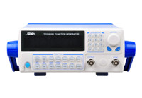

This is how to use a function generator to test a circuit’s behavior:
Power on the Cheap 20MHz Function Generator and select the desired output signal: square wave, sine wave or triangle wave.
Connect the output leads to an oscilloscope to visualize the output signal and set its parameters using the amplitude and frequency controls.
Attach the output leads of the function generator to the input of the circuit you wish to test.
Attach the output of your circuit to a meter or oscilloscope to visualize the resulting change in signal.

Jul. 10, 2025
Common Uses and Types of Signal GeneratorsJun. 13, 2025
Power Quality Analyzers: SA2100, SA2200, and SA2300 – Which One Fits Your Workflow?May. 14, 2025
Stopwatch Calibrator Uses in Aerospace, Automotive and Labs